¶ Variable Management
AutomationView manages PLC variables through automatic discovery in your sequences and explicit declaration in the Machine Editor and Variables sidebar.
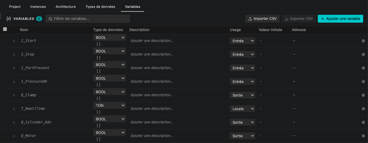
¶ Creating and Managing Variables
You can create and configure variables using three workflows:
- Machine Editor -> Variables Tab:
- Open
main.machineand select the Variables tab. - Click Add variable to declare a new variable with its type, initial value, usage, and description.
- Click the Freeze icon next to any inferred variable to save an explicit declaration in
main.machine.
- Open
- Variables Sidebar:
- Open the Variables panel in the AutomationView sidebar.
- Click Add Variable in the panel toolbar, or right-click a variable and select Declare in main.machine (Freeze).
- Automatic Discovery in Sequences:
- Type a new variable name directly in a transition condition or action inside the Sequence Editor.
- AutomationView automatically registers the variable and infers its data type from context.
¶ Bulk Import, Export, and Spreadsheet Paste
Manage large variable tables in the Machine Editor Variables tab:
- Import CSV: Click Import CSV (or run AutomationView: Import Variables from CSV) to load variable definitions from a
.csvfile. - Export CSV: Click Export CSV (or run AutomationView: Export Variables to CSV) to save the project variable table to a
.csvfile. - Spreadsheet Paste: Copy cells from Excel or another spreadsheet (
name,type,description,usage,initial value) and press Ctrl+V inside the Variables tab.
¶ Data Types
¶ Elementary IEC 61131-3 Types
| Type | Description | Example |
|---|---|---|
BOOL |
Boolean (TRUE / FALSE) |
sensor_1, motor_on |
INT |
16-bit signed integer | part_count, speed |
DINT |
32-bit signed integer | encoder_pos, total_count |
REAL |
32-bit floating point | temperature, pressure |
LREAL |
64-bit floating point | high_precision_pos |
STRING |
Text string (supports fixed length STRING[80]) |
recipe_name, barcode |
TIME |
Duration literal (T#5s, T#100ms) |
cycle_delay |
BYTE |
8-bit unsigned bit string | status_byte |
WORD |
16-bit unsigned bit string | status_word |
DWORD |
32-bit unsigned bit string | fault_mask |
¶ Arrays
Any elementary, compound, or custom data type can be configured as a single-dimensional or multi-dimensional array:
- In the Variables tab or Datatypes tab, open the type selector for a variable or struct field.
- Enable Array and specify the dimension bounds (for example
[0..9]or[-5..10, 1..4]). - Access array elements in conditions and actions using standard bracket syntax (for example
buffer[0],matrix[i, j]).
¶ Custom Types (STRUCT and ENUM)
Define reusable data structures and enumerations in the Machine Editor Datatypes tab:
STRUCT: Group related fields of any type (including nested structs and arrays) and access them with dot notation (for examplestation_data.cylinder.extended).ENUM: Define named states (for exampleMode.AUTO,Mode.MANUAL) for readable conditions and assignments.
¶ Compound Types (Timers & Counters)
Compound types represent IEC 61131-3 function blocks. Access their member fields using dot notation (for example delay_timer.Q).
| Type | Fields | Description |
|---|---|---|
| TON | .IN, .Q, .PT, .ET |
On-delay timer |
| TOF | .IN, .Q, .PT, .ET |
Off-delay timer |
| TP | .IN, .Q, .PT, .ET |
Pulse timer |
| RTO | .IN, .R, .Q, .PT, .ET |
Retentive on-delay timer |
| CTU | .CU, .R, .Q, .PV, .CV |
Count-up counter |
| CTD | .CD, .LD, .Q, .PV, .CV |
Count-down counter |
¶ Usage Context and I/O Addressing
Variables are organized by usage context:
| Usage Context | Address Area | Description |
|---|---|---|
| Input | %I |
Wired to a physical input channel (sensors, buttons) |
| Output | %Q |
Wired to a physical output channel (valves, motors) |
| Local | - | Internal project or sequence variable |
¶ Address Format
I/O addresses are computed automatically when you bind a variable to an equipment channel in the Machine Editor Architecture tab:
%IX2.0   -> Input bit, byte offset 2, bit 0
%QW4     -> Output word, byte offset 4
%IB1     -> Input byte, offset 1
%QD8     -> Output double word, offset 8
¶ Address Assignment Commands
- Assign Addresses (Manual): Opens the Machine Editor Architecture tab to bind variables to module channels in the grid.
- Assign Addresses (Automatic): Automatically assigns non-conflicting
%Iand%Qaddresses to unassigned channels. - Validate Addresses: Checks the project for duplicate or conflicting hardware addresses.
¶ Variable Commands
Run variable commands from the Command Palette (Ctrl+Shift+P) or the Variables sidebar:
| Command | Description |
|---|---|
| Add Variable | Create a new variable declaration in main.machine |
| Declare in main.machine (Freeze) | Persist an inferred variable into main.machine |
| Rename Variable | Rename a variable across all .seq and .machine files |
| Import Variables from CSV | Import variable declarations from a CSV file |
| Export Variables to CSV | Export the project variable table to a CSV file |
| Get Variable Value | Read a live variable value during simulation |
| Set Variable Value | Write a variable value during simulation |
| Assign Addresses (Manual / Auto) | Map variables to hardware channels in the Machine Editor |
| Validate Addresses | Check for hardware address conflicts |
¶ See Also
- Machine Editor - Manage variables, custom datatypes, and hardware architecture
- Variable Scope Reference - How local, global, I/O, and instance scopes work
- Smart Diagnostics - Type checking, array bounds, and address validation
- Smart Completion - Autocomplete for variables, struct fields, and enum values