Festo CPX and Valve Terminal Integration Guide
Model a decentralized Festo CPX valve island in AutomationView: a fieldbus node, a VTUG valve terminal, and the variables that drive each solenoid coil.
1. Festo Hardware Topology
A typical pneumatic island sits on the machine fieldbus. The PLC talks to a CPX bus node, and the valve terminal and I/O modules hang behind it:
[PLC (Siemens / Rockwell / CODESYS)]
                |
     (PROFINET / EtherNet/IP / EtherCAT)
                v
       [Festo CPX bus node]
         /             \
        v               v
  [VTUG valve      [Digital input
   terminal]        module (sensors)]
The Festo plugin is an equipment catalog. It does not generate PLC code of its own: you export the sequences for the PLC that drives the bus node (Siemens, Rockwell, or CODESYS).
2. Festo Equipment in the Catalog
Open the Equipment Catalog view in the AutomationView side bar and expand Festo. The catalog contains, among others:
| Family | Catalog IDs | Role |
|---|---|---|
| CPX bus nodes | festo-cpx-fb13 (PROFIBUS DP), festo-cpx-fb33 (PROFINET), festo-cpx-fb36 (EtherNet/IP), festo-cpx-fb37 (EtherCAT) |
Fieldbus interface of the CPX terminal |
| CPX I/O | festo-cpx-8de, festo-cpx-16de, festo-cpx-8da, festo-cpx-4ae-u-i, festo-cpx-2aa-u-i |
Digital and analog inputs and outputs |
| CPX-AP-I I/O | festo-cpx-ap-i-8di-m8-3p, festo-cpx-ap-i-8do-m8-3p, festo-cpx-ap-i-4iol-m12 |
Decentralized I/O and IO-Link master |
| CPX-E | festo-cpx-e-ep, festo-cpx-e-16di, festo-cpx-e-8do, festo-cpx-e-cec-c1 |
Modular I/O system and controllers |
| Valve terminal | festo-vtug |
VTUG valve terminal |
| Drives | festo-cmmt-as-..., festo-cmmt-st-... |
CMMT servo and stepper drives |
The festo-vtug entry has three versions, one per VAEM electrical interface: VAEM-L1-S-8-PT, VAEM-L1-S-16-PT, and VAEM-L1-S-24-PT (8, 16, or 24 solenoid coils). Each coil is an output channel named Valve Solenoid 0, Valve Solenoid 1, and so on. A double-solenoid valve uses two coils. The Valve Size parameter (10, 14, or 18 mm) records the width of the fitted valves.
3. Build the Island in the Architecture Tab
Open main.machine in the Machine Config Editor and select the Architecture tab. Each station lists its modules by slot, with the channel occupancy of each module, and the Equipment Catalog panel stays open on the right:
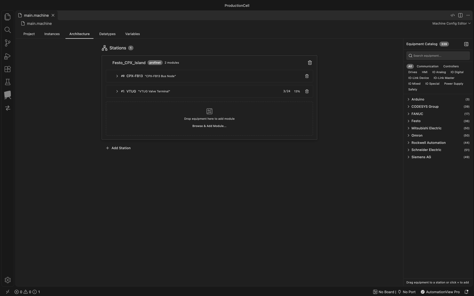
Station Festo_CPX_Island: slot #0 holds the CPX-FB13 bus node, slot #1 the VTUG valve terminal with 3 of its 24 coils assigned.
- Click Add Station, enter a label such as
Festo_CPX_Island, and choose the station Protocol (for exampleprofinet). - Add the bus node: drag it from the Equipment Catalog panel onto the station, or click Browse & Add Module... and pick it in the list. For a PROFINET network, choose
festo-cpx-fb33. - Add the valve terminal the same way and select the version that matches the VAEM interface you ordered.
- In the channel grid of the VTUG module, select a variable for each coil you use. Unused coils stay (unassigned).
The same island in Python, inside setup() of main.machine:
island = self.add_station("Festo_CPX_Island", protocol="profinet")
island.add_module("festo-cpx-fb33", label="CPX-FB33 Bus Node")
valves = island.add_module("festo-vtug", version="VAEM-L1-S-24-PT", label="VTUG Valve Terminal")
valves.assign("V0", "cmd_Cyl1_Extend")
valves.assign("V1", "cmd_Cyl1_Retract")
valves.assign("V2", "cmd_Cyl2_Extend")
valves.assign("V3", "cmd_Vacuum_Eject")
4. Coil-to-Variable Mapping
Give each coil a name that says what the actuator does, not where it is wired:
| VTUG Channel | Variable Name | Physical Coil / Function |
|---|---|---|
| Valve Solenoid 0 | cmd_Cyl1_Extend |
Valve 0, coil 14: clamp extend |
| Valve Solenoid 1 | cmd_Cyl1_Retract |
Valve 0, coil 12: clamp retract |
| Valve Solenoid 2 | cmd_Cyl2_Extend |
Valve 1, coil 14: transfer extend |
| Valve Solenoid 3 | cmd_Vacuum_Eject |
Valve 2, coil 14: vacuum generator on |
Run AutomationView: Assign Addresses Automatically to compute the %Q addresses from the channel offsets, then AutomationView: Validate All Addresses to check for conflicts before export. See I/O to PLC Export Workflow for the full sequence.
5. Pressure and Fault Monitoring
The catalog does not add diagnostic variables for you. Declare the signals you need as ordinary inputs and wire them to input channels:
I_PressureOK: pressure switch confirming the supply pressure.I_ValveFault: fault signal of the valve terminal or bus node, as provided by your PLC program.
Include I_PressureOK in the start conditions of your GEMMA Master Sequence and in the watchdog transitions of each cylinder.
See Also
- Festo Extension Reference: Catalog parts and technical data
- Pneumatic Cylinder Standard: Motion watchdog patterns
- End-to-End Machine Tutorial: Festo pick-and-place cell